Schematics
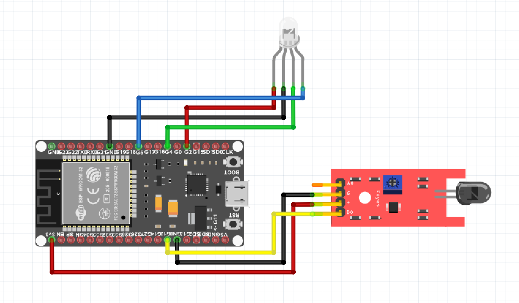
In this section, you will find the wiring diagram of how to connect the Photodiode and Status LED to the ESP board of your choice.
Wiring diagram
Below you will find a wiring diagram of how everything is connected, depending on the type of board you use, the GPIO pins may be in a different place. You could also omit the status LED if desired.

important
Please note that there are different boards in circulation and that the GPIO pins may be on a different location than in the example above. So always double check and, if necessary, consult the pin layout of your specific board.