Diagrams
On this page you will find GPIO pin tables for the Photodiode and Status LED, as well as a wiring diagram of how everything is connected.
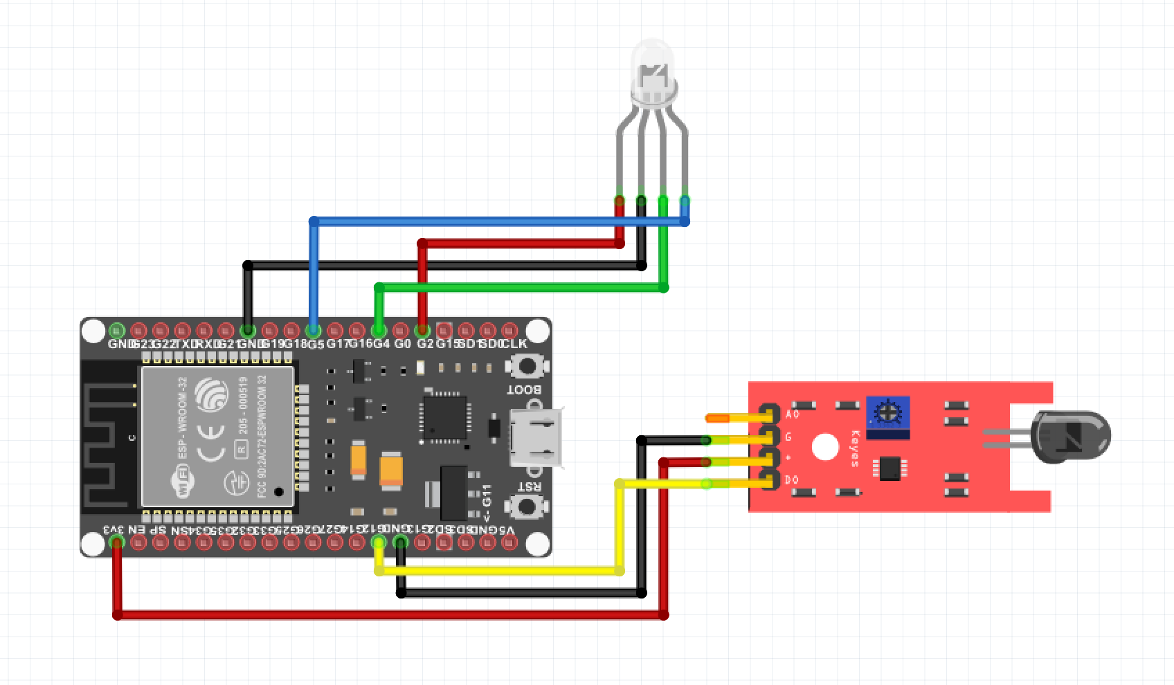
Wiring diagram
Below you will find a wiring diagram of how everything is connected, depending on the type of board you use, the GPIO pins may be in a different place. You could also omit the status LED if desired.
GPIO pins
In the tables below you will find more information, about how to connect the Photodiode PCB and the status LED.
Photodiode
How the Photodiode is connected to the ESP board of your choice.
| PHOTODIODE | ESP32 | Wemos D1 / ESP8266 |
|---|---|---|
| A0 | NOT USING | NOT USING |
| DO | D26 (GPIO26) | D7 (GPIO13) |
| VCC | 3V3 | 3V3 |
| GND | GND | GND |
Status LED
How the status LED is connected to the ESP board of your choice. For each measured pulse, the LED will briefly flash red and in case of no WiFi connection, the LED will continue to flash blue.
| LED | ESP32 | D1 mini / ESP8266 |
|---|---|---|
| RED | D2 (GPIO2) | D4 (GPIO2) |
| GREEN | D4 (GPIO4) | D2 (GPIO4) |
| BLUE | D5 (GPIO5) | D1 (GPIO5) |
| GND | GND | GND |